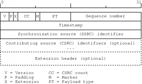
Figure 5.1: The RTP header [30]
We now know how to send voice information without wasting a lot of bandwidth so we can move on to issues relating to the actual transmission of the speech data. The Internet Protocol only offers a best-effort service without any QoS guarantees. For decent voice communication it is, however, necessary to have certain guarantees since too much delay or too many lost packets will seriously affect the quality of the conversation.
This chapter discusses how we can transmit voice information while preserving the communication quality. First we will talk about some general requirements. Next, we will see what protocols can be used to transmit the speech data. Also, some resource reservation methods will be discussed since this can help to improve the transmission quality. Finally, we will discuss the transmission delay.
When transmitting packets containing voice data, there must be some mechanism to preserve synchronisation within the speech signal. The consecutive packets should be played at the right time, in the right order. This type of synchronisation is called intra-media synchronisation.
We have seen in chapter three that for real-time voice communication, the overall delay has to be kept as low as possible. Since an IP network in general only offers a best-effort service, there is no guarantee that the delay will meet the requirements. Similarly, the amount of lost packets can be quite high, for example during periods of congestion. To be able to deliver telephone quality speech, there will have to be some quality of service (QoS) mechanism which offers guarantees about these things.
The speech data which has to be sent is typically generated at regular small intervals. It is possible that a receiving end cannot cope with this data flow, so somehow the sender should know whether the receiver can handle the incoming stream or not. A method that does this is often called a flow control method.
Also, due to the fact that data is sent at a regular basis, it is not unlikely that a link becomes overloaded and congestion occurs. In turn, congestion causes the loss of packets and an increase in delay which are not desirable features for voice communication. The transmission component should be able to detect an arising congestion and take appropriate actions. The mechanism to prevent and control congestions is called congestion control.
The appropriate action for flow and congestion control is to decrease the amount of data sent. Typically, this is done in cooperation with the compression module: when the data rate has to be lowered, the compression module is signalled to increase the amount of compression. This will usually result in a degradation of speech quality, but it is still better than having a lot of lost packets and a large delay.
If an application wants to transmit data, it uses a certain protocol to do this. Recall that in the TCP/IP architecture, TCP and UDP are the protocols which an application can use.
First, we will see why the bare TCP and UDP services are not sufficient. Then, a description of the Real-time Transport Protocol (RTP) is given. This is a widely used protocol for real-time data like speech and video.
When we are thinking about VoIP applications which should offer a telephone-like service, TCP could seem a good candidate to transmit the speech data. It offers a service in which the connection can be seen as a reliable byte stream. To use TCP, a connection is set up, data is exchanged and the connection is torn down again. This procedure immediately reminds one of the way a telephone call is made.
When it comes to synchronisation, the reliable byte stream service seems like a very good starting point: all data arrives nicely in the exact same order as it was transmitted. Also, data is guaranteed to arrive correctly, which is also good for voice communication. The protocol also has built-in flow and congestion control mechanisms which offer good protection against overloading the network.
There are however, several disadvantages to the use of TCP. One of the basic problems is that to offer this reliable byte stream service, the protocol relies heavily on the retransmission of lost or corrupted packets. While this offers a reliable service in which order is preserved, the waiting for retransmitted packets adds extra delay to the communication. Usually, it is better to have an occasional lost or corrupted packet than having a large amount of delay.
A related issue is that one lost or corrupted packet effectively prohibits the application of receiving any packets which come after it, since TCP preserves the order of the packets. The application has to output speech data at regular intervals, so if one packet stays lost for a sufficient amount of time, this will block the playback of other packets, even when they have already arrived.
The flow and congestion control features might seem very useful, but an application has very little control over these things. TCP can easily decide by itself to decrease the rate at which data is sent, and this again would increase the overall delay.
The key point to be made here is that TCP has a lot of features and a lot of complexity which are not very useful for VoIP. We could easily get an equal or better performance using far less elaborate protocols.
When speech data has to be distributed to several users at the same time, TCP has another major disadvantage. While IP offers the efficient distribution of data using multicasting, TCP has no support for this. If data has to distributed to several destinations using TCP, it has to be done using separate TCP connections. This, of course, wastes a lot of bandwidth.
When we eliminate TCP, the only basic protocol we can use is UDP. This protocol has almost no complexity at all. It is simply a minor extension to IP, so it offers only a best-effort service.
The protocol has the advantage of not having to wait for retransmissions of lost packets. Also, since it is only a small extension to IP, it can make use of the IP multicasting features and save bandwidth when data has to be sent to multiple destinations. As good as all this may seem, there are also some disadvantages: UDP provides no mechanism for synchronisation whatsoever and there are no means for flow or congestion control.
A solution to these problems is to extend UDP somewhat: we can add extra information to the speech data and use UDP to distribute this control and speech information. This is in fact how the Real-time Transport Protocol (RTP) works in the TCP/IP architecture.
The Real-time Transport Protocol is formally specified in [30]. There, it is defined as a protocol which provides end-to-end delivery services for data with real-time characteristics, such as interactive audio and video. So this protocol can also be used for VoIP applications.
The RTP specification actually defines two separate protocols. The first one is the Real-time Transport Protocol (RTP). The second one is called the RTP Control Protocol (RTCP). The function of RTP is to transfer the real-time data. The control protocol supplies information about the participants in the session. The protocols are defined in such a way that they can be used on a lot of network architectures and not just on TCP/IP networks. However, if RTP is used on a TCP/IP network, it is typically run on top of UDP.
The protocols themselves do not provide mechanisms to ensure timely delivery. They also do not give any QoS guarantees. These things have to be provided by some other mechanism.
Also, out of order delivery is still possible, and flow and congestion control are not directly supported. However, the protocols do deliver the necessary data to the application to make sure it can put the received packets in the correct order. Also, RTCP provides information about reception quality which the application can use to make local adjustments. For example if a congestion is forming, the application could decide to lower the data rate.
In the following sections, an introduction to RTP and RTCP is given. These sections are based on the specifications in [30], which is also the appropriate source to consult for more detailed information about these items.
Personally, I have used RTP in the VoIP applications which I developed. For this purpose I first wrote a RTP library, which is described in chapter eight.
A RTP packet consists of a RTP header, followed by the data to send. In the RTP specification this data is referred to as the payload. The header is transmitted in network byte order, just like the IP header. Figure 5.1 shows the RTP header format.
The first two bits of the header contain the version number. The current version of the protocol is `two'. Next, there is the padding bit. If this bit is set, the packet contains some padding bytes which are not part of the payload. The last padding byte then contains the number of padding bytes. For example, padding may be necessary for some encryption algorithms which need the payload to be aligned on a multiple byte boundary. The extension bit specifies if the header contains an extension header. Then, there is the CSRC count which specifies how many contributing sources are specified in the RTP header.
The marker bit can be used by an application to indicate a talkspurt for example. The exact interpretation is not defined in the RTP specification, it is left to the application itself. Next, there is the payload type. This defines the type of data the packet contains, so it defines the way in which the application will interpret the payload.
The sequence number can be used by an application to place received packets in the correct order. The numbering starts at a random value for security reasons.
The timestamp contains the synchronisation information for a stream of packets. This value specifies when the first byte of the payload was sampled. For example, for audio, the timestamp is typically incremented with the amount of samples in the packet. Based on this value, the receiving application can then play the audio data at exactly the right time. Just like with the sequence number, the initial value of the timestamp is random. Note that several packets can have the same timestamp value: with digitised video for example, one image will usually have to be sent in several pieces. These pieces will all have a different sequence number, but their timestamp value will be the same.
The synchronisation source (SSRC) identifier is the identification number of the sender of the packet. If an application wishes to send different media at the same time, for example audio and video, there have to be separate RTP sessions for each of the media. This way, an application can group the incoming data according to the SSRC value. The identifier is chosen randomly; the chance that two communicating parties accidentally end up having the same SSRC value is extremely small. In the rare case that this should happen, the specification gives the appropriate course of actions to resolve this problem.
Next, there are possibly a number of contributing source (CSRC) identifiers. For example, if at some point different audio streams have to be mixed together, the original SSRC identifiers can be put here. The SSRC identifier of this packet then becomes the identifier of the source which forwards the mixed packet.
Finally, the header can contain extra information through the use of an extension header. The RTP specification only defines the extension mechanism, not the possible extensions. This is left to the application.
Note that the header does not contain a payload length field. The protocol relies on the underlying protocol to determine the end of the payload. For example, in the TCP/IP architecture, RTP is used on top of UDP, which does contain length information. Using this, an application can determine the size of the whole RTP packet and after its header has been processed, it automatically knows the amount of data in its payload section.
The RTP protocol is accompanied by a control protocol, RTCP. Each participant of a RTP session periodically sends RTCP packets to all other participants in the session. According to [30], RTCP has four functions:
There are several types of RTCP packets which are used to supply this functionality. Sender reports (SR) are used by active senders to distribute transmission and reception statistics. If a participant is not an active sender, it still distributes reception statistics by sending receiver reports (RR). Information which describes a participant is transmitted in the form of source description (SDES) items. There is also a packet type to allow application specific data (APP). Finally, when a participant is about to leave the session, it sends a goodbye (BYE) packet.
The transmission statistics which an active sender distributes, include both the number of bytes sent and the number of packets sent. It also includes two timestamps: a Network Time Protocol (NTP) timestamp, which gives the time when this report was created, and a RTP timestamp, which describes the same time, but in the same units and with the same random offset of the timestamps in the RTP packets.
This is particularly useful when several RTP packet streams have to be associated with each other. For example, if both video and audio signals are distributed, on playback there has to be synchronisation between these two media, called inter-media synchronisation. Since their RTP timestamps have no relation whatsoever, there has to be some other way to do this. By giving the relation between each timestamp format and the NTP time, the receiving application can do the necessary calculations to synchronise the streams.
A participant to a RTP session distributes reception statistics about each sender in the session. For a specific sender, a reception report includes the following information:
The source description items give general information about a participant, like name and e-mail. But it also includes a so-called canonical name (CNAME). This is a string which identifies the sender of the RTP packets. Unlike the SSRC identifier, this one stays constant for a given participant, independent of the current session and it is normally unique for each participant. Thanks to this identifier it is possible to group different streams coming from the same source.
Since these packets are sent periodically by each participant to all destinations, we have to be careful not to use too much of the available bandwidth for RTCP packets. The RTCP packet interval is calculated from the number of participants and the amount of bandwidth which RTCP packets may occupy. To prevent that each participant would sent its RTCP packets at the same time, this value is multiplied by a random number.
Now that we have a decent protocol which we can use to transmit the digitised speech, we need to address another matter. With RTP, we can transmit packets containing voice information, but what should the size of these packets be?
We have already seen in a previous chapter that packets containing only a small amount of voice data are desirable for two reasons. First, if a packet gets lost, it does not cause a severe distortion in the communication. Second, to reduce the overall delay, the sampling interval should be as low as possible and each piece of the digitised voice signal should be transmitted as soon as possible. This automatically implies small packet sizes.
But we have to keep in mind that when this speech data is transmitted, a part of the bandwidth will be occupied with headers of the underlying protocols. So, the smaller the time interval captured in a packet, the larger is the overhead caused by headers.
Consider the following example. A voice signal is sampled at regular intervals of one millisecond. After each sample interval we will transmit the digitised signal using RTP. This means that every millisecond, at least a RTP, UDP and IP header is actually transmitted over some medium. Their total size is at least forty1 bytes. Sending forty bytes each millisecond needs a bandwidth of 320 kbps!
It is obvious that if we increase the sampling interval, the bandwidth occupied with only header information will decrease. This will result in a larger overall delay, so we must be careful not to make the sampling interval too large. It will also result in larger packet sizes which causes the communication to be more vulnerable to lost packets.
Clearly, somehow a compromise will have to be made. Usually, sampling intervals of ten to thirty milliseconds are used, since these are the sampling intervals which a lot of compression techniques use. When bandwidth is scarce, perhaps even a larger values are advisable.
With dial-up links, the available bandwidth is very low compared to the available bandwidth on a LAN for example. In this case, we would like to have as much bandwidth available for the actual data as possible. Luckily, there exist methods to greatly reduce the bandwidth occupied by header information on such links.
When you are using a dial-up link, a lot of consecutive packets will go to the same destination application. This means that many IP and UDP header fields stay the same. When RTP is used on top of UDP, a number of fields in the RTP header will also stay the same, while the values of other fields change with a fixed amount for each packet. Using this information, the aggregate header size of forty bytes can be reduced to two to four bytes! This, of course, greatly reduces the bandwidth occupied by header information. The exact way to do all this is specified in [8].
We mentioned before that RTP itself offers no way to achieve certain levels of QoS, it relies on external methods to provide this. There are several ways in which this can be done. This section gives an overview of such methods.
Both IPv4 and IPv6 have a way to specify the priority of a datagram. In the IPv4 header some level of QoS can be specified in the TOS field. The IPv6 header has a similar feature through the use of the traffic class field.
If all routers take such priorities into account, this could help real-time data to be delivered with, for example, low delay. The main advantage of this approach is that no additional protocols are needed. The only thing that needs to be done is to adjust routers so they can take the priorities of packets into account.
But these mechanisms can only help to give a better service, they cannot give any guarantees whatsoever. For example, if the whole network is filled with high-priority traffic, the quality will still be poor.
So we have to rely on other means if we want to be able to provide guarantees about QoS. In the following sections we will explore two protocols which are designed for this purpose. First, an explanation of version two of the Stream Protocol (ST2) is given. Next, I will describe the Resource Reservation Protocol (RSVP). To give guarantees about QoS, both of these methods rely on the reservation of resources. The way this is done in each of these cases differs greatly. Therefore, a section with a comparison of their basic techniques is presented afterwards.
The Stream Protocol version two (ST2) was first specified in [13]. This document was released in October 1990. Five years later, after gaining experience with the protocol, it was revised and redefined in [22]. The main goal of the revision was to simplify the protocol and to clarify some issues. Also, some extensions were added. The basics of ST2 remained the same however. The information in this section was obtained from the two mentioned references.
Within the TCP/IP architecture, ST2 is situated in the internet layer. Its purpose is to provide an end-to-end guaranteed service across an internet. The protocol is not intended as a replacement for IP, but as an addition. This way, general data transfers can still use IP while real-time data can be transmitted using ST2.
Unlike IP, which is a connectionless protocol, ST2 is connection-oriented. This implies that to transfer data, there are three stages involved. First, the connection has to be set up. During this stage, resources are reserved to be able to provide certain QoS guarantees. When the ST2 connection has been established, the actual data transfer can take place. When all data has been transmitted, the connection has to be released again.
A connection will only allow the flow of data in one direction: from the origin to the destinations. If communication in the other direction has to be possible, a different ST2 connection will have to be made. This way, the connection can be represented by a directed tree, from the origin to the destinations. Using this model, the distribution of data will be done in such a way as to minimise the amount of duplicate packets sent.
To create a connection, an application must first know a number of targets to connect to. For this purpose, the application cannot use ST2 itself, it must use some other means. Probably, some IP based protocol will be used to do this.
When the application knows the destinations and the necessary QoS constraints, it can deliver this information to the ST2 module and ask it to set up a connection to these destinations. Within ST2 the QoS constraints are distributed by means of a flow specification, also called FlowSpec.
Based upon the information in this FlowSpec, the intermediate ST2 supporting routers can make the necessary reservations. If these reservations do not correspond to the desired QoS, the information in the flow specification is updated to reflect the actual obtained QoS at the current point.
When a destination receives the connection request, this FlowSpec can be investigated by the application and it can decide whether to accept the connection or not. If the connection is accepted, the FlowSpec with the acquired QoS values is propagated back to the origin of the connection request.
If all goes well, the application which attempted the connection, receives a confirmation of each destination. These confirmations also contain a FlowSpec describing the obtained QoS for each target. The application can then decide whether to start sending its data or to abort the connection.
Note that at different stages along the path from origin to destinations, the reservations can differ. The application has to explicitly release any excess reservations.
During the lifetime of the connection, there is still a possibility to add destinations. The procedure is similar as the creation stage and it is started by the origin of the connection. Destinations can also be removed from the connection. This can be done by the origin or the destination itself.
Only the data packets are in fact transmitted using ST2. Other functions are provided through the use of a control protocol: the ST Control Message Protocol (SCMP). These functions include connection creation and adding destinations. All control messages are transmitted reliably, using acknowledgements and retransmissions if necessary.
To be able to detect the failure of network elements, each ST2 capable machine periodically sends a `hello' message to each of its neighbours. If necessary, recovery procedures will be initiated.
Note that ST2 itself does not specify how the reservations should actually be made or how the QoS itself should be provided. It only presents a way to distribute the desired QoS specifications.
Another way to reserve resources is by using the Resource Reservation Protocol (RSVP). This protocol is specified in [29]. The protocol is a part of an Integrated Services model, described in [17]. The term Integrated Services refers to the fact that several kinds of services can be offered, for example both real-time and best-effort services.
Unlike with ST2, RSVP does not provide its own data transmission protocol. This function is still performed by IP. RSVP is merely a control protocol which can be used to help provide QoS guarantees to applications. The protocol can be used with both IPv4 and IPv6.
If a host is going to transmit data which should arrive with a certain QoS, it periodically sends a so-called path message to the destination of the data. This address can be both a unicast or multicast address. The path message contains information about the characteristics of the traffic that will be generated by this sender. Also, the format of its data packets is described. Using this information it is be possible to select packets from this specific sender out of others.
On its way to the destinations, RSVP capable routers store the information in the path message. This way, it can be used when reservations will be made for data coming from the sender of the path message.
When an application receives a path message, it can decide it wants to receive the sender's data with a specific QoS. It can determine the necessary QoS constraints from the information contained in the path message. To request this QoS, it will periodically send a reservation request along the reverse path of the path message. The exact reverse path can be followed because of the saved information in RSVP capable routers in response to the path message.
The reservation request contains two items. First, it contains the QoS which the receiver would like to obtain. Second, it contains a description of the set of data packets which should be received with this QoS.
Inside each router, the necessary reservations can be made to supply the QoS. An important feature of RSVP is that reservations may be merged. After a merge, the router checks if there is a net change for the link upstream, and if so, an appropriate reservation request is sent to the previous router.
Lets illustrate this with a small example. Consider the situation in figure 5.2. Suppose host A is the sender and is distributing digitised speech as part of an on-line conference. This data is being distributed by sending it to a multicast address to which path messages have also been sent. Host B in response, has issued a reservation request which caused the reservation of 32 kbps along the path from host A to B.
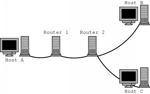
Now host C also joins the conference and wishes to have a guaranteed 16 kbps link with host A. The host creates a reservation request which specifies this and sends it to router 2. There, the router investigates the request and reserves bandwidth of 16 kbps downstream over the link to host C. It also notices that upstream, there is already a reservation of 32 kbps to host A, so no extra reservation request will have to be sent to router 1. If, however, host C would have requested 64 kbps, a new reservation would have been forwarded to router 1.
Several reservation styles are supported by RSVP. For example, if a host receives data from many sources, it could issue a reservation request which would allocated separate bandwidth for each source. But it is also possible to specify that the allocated bandwidth should be shared by all senders. This is useful in case of an on-line discussion where there will be usually only one speaker at a time. It would then be sufficient to allocate bandwidth to accommodate only one or a few speakers.
Note that the path messages and reservation requests are sent periodically. This is because the RSVP information within a router will time out after a while. To keep the path information and reservations in place, they have to be updated regularly. This is called a soft-state mechanism. When a reservation or path state times out, the associated resources can be released. Resources can also be released explicitly when a sender or receiver quits.
Like ST2, RSVP does not specify how actual QoS guarantees have to be enforced. The protocol is only used to distribute the QoS related information.
Both ST2 and RSVP provide a mechanism which can be used to make resource reservations along the path from sender to receivers. These resource reservations are intended to supply QoS guarantees. With both protocols, the resources are allocated for data distribution in one direction only: from sender to receivers. This can be modelled as a directed tree, with the root being the sender.
But the approach that these protocols follow differs significantly. So the question arises which one is the most efficient. In [5] a comparison is made between the two protocols. Here, I will summarise the key differences.
An important difference is from where the reservation requests originate. With ST2, it is the sender which makes the necessary reservations along its distribution path. In contrast, with RSVP the receivers request the reservations. For this reason, ST2 is often said to have a sender initiated reservation style, while RSVP 's reservation style is called receiver initiated.
For some applications, there will be several senders, but there will usually be only a few of them sending at the same time. Like was mentioned above, with RSVP this knowledge can be exploited through the use of a specific reservation style. ST2 however, does not have such a feature. Here, reservations will have to be made for each possible sender and this, of course, wastes a lot of bandwidth.
When data is distributed to a number of receivers, it is very unlikely that all these receivers will have the same QoS demands. Since ST2 is sender-initiated, the sender will have to request reservations to satisfy the needs of the most demanding receiver. Even branches that lead to less demanding receivers will all have the same reservations.
With RSVP, the heterogeneity of receivers is handled much more efficiently. The requests originate from the receivers themselves and if possible, requests are merged. This means that branches of the distribution tree which lead to less demanding receivers, will have less reservations. A previous example already illustrated this.
When a receiver is unable to accommodate data streams from all active senders, it may wish to be able to dynamically select from which sources to receive data. This is called channel selection. With ST2, the only possibility for channel selection is to make a separate reservation for each sender. The actual channel selection will have to be done at the receiver.
Recall that a RSVP reservation request contains a description of which packets should receive the associated QoS. This way, when a reservation request is sent, a new set of sources can be selected and filtering can be done inside the network.
Network failure detection in ST2 is done by periodically sending messages to neighbouring machines which participate in the same stream. If an error is detected, a recovery procedure is started. RSVP completely relies on the soft-state mechanism to automatically adapt to any failures. Note that both protocols send messages periodically. With RSVP however, the overhead of these messages is reduced by merging reservation requests were possible.
When a receiver joins a ST2 session, the reservations for this receiver have to be requested by the sender. This way a message will have to travel all the way from the sender to the new receiver. With the receiver-initiated approach of RSVP, a reservation request is only propagated towards the sender until it can be merged with other reservations. This results in less protocol overhead. However, the receiver may have to wait a while to send its request until it receives a path message.
When resource reservation methods are supported in routers, transmission delays can probably be kept low enough to satisfy the overall delay constraint of 200 ms. But at this time, routers which are currently used in general do not have such capabilities.
When data is transmitted there is always a minimal amount of delay due to the capacity of the links along which the data travels. But the most significant part of the delay by transmission is usually due to queuing of packets inside routers. This delay is highly variable and depends both on the number of routers along the path and the load of the routers.
It is not possible to make a general claim about transmission delay in IP networks, although one-way transmission delays rarely tend to exceed 100 ms [41]. However, it is not inconceivable that this delay can exceed 200 ms.
When we want to transmit speech data, there are several things which we have to keep in mind. Some mechanism has to be used to preserve intra-media synchronisation. Measures should be taken to guarantee a low overall delay and somehow flow and congestion control should be possible.
In the TCP/IP architecture, an application can use either TCP or UDP to transmit data. To transmit voice information, TCP might seem like a good choice because it offers a reliable byte stream service with flow and congestion control. But this reliability is achieved by the retransmission of lost packets, which causes the overall delay to increase. An increase in delay can also be caused by the flow or congestion control mechanisms, over which the user has little control.
The other protocol, UDP, is not sufficient for real-time data, as it does not provide any means for intra-media synchronisation or flow or congestion control. A solution to this problem is to extend UDP somewhat. This is the way RTP is used in the TCP/IP architecture.
The Real-time Transport Protocol (RTP) provides extra information which can be used for synchronisation within a data stream. The RTP Control Protocol (RTCP) provides additional information which can be used for inter-media synchronisation, flow and congestion control and identification.
Each piece of speech data which is transmitted will have a number of headers sent along with it. These headers also occupy a part of the bandwidth, so to reduce the header overhead, packets should not be too small. For dial-up links, extra bandwidth savings can be achieved by using header compression techniques.
To provide quality of service (QoS), one could use the priority information in the IP header. This method can improve the QoS, but it cannot offer any guarantees. Other protocols like ST2 and RSVP can be used to do this. Both of these give QoS guarantees by making resource reservations.
The Stream Protocol version two (ST2) uses a sender initiated reservation model: the sender issues the resource reservation requests along the path to the receivers. It is a connection-oriented protocol, which serves as an addition to IP.
The Resource Reservation Protocol (RSVP) on the other hand, uses a receiver initiated approach. The sender distributes a description about the data which is being sent and the receivers can make resource reservations for this data. It is a soft-state mechanism: the senders and receivers have to send this information periodically because the associated resources will be released otherwise. RSVP also merges reservations where possible. This protocol seems to be more efficient than ST2.
The transmission of a packet introduces an amount of delay into the communication. This delay is highly variable due to the queuing delays in routers.