
Figure 2.1: Example of layered design [9]
Before we can really talk about Voice over IP, it is necessary to explain what IP is. The abbreviation IP stands for Internet Protocol. Version four is currently most in use and it is common to use the term `IPv4' to indicate this version of the protocol. When no version number is mentioned, usually the discussion is about version four. This is also the case in this thesis.
The Internet Protocol is covered in this chapter. It begins with a discussion about network software architecture, followed by a description of the workings of IP. We will also see some characteristics of IP networks and I will describe the most used protocols which run on top of IP. Afterwards, some reasons will be given for the use of IP for voice communication. Finally, the chapter contains an overview of IPv6, the new version of the Internet Protocol. The information in this chapter was mostly obtained from [34], [9] and [41]. The official specification of IPv4 can be found in [19].
Nowadays, network software is usually very structured. This section is about the way this software is organised. It also contains a discussion about the OSI reference model, which is a good example of this structured design, and about the TCP/IP reference model, in which - as the name suggests - IP plays a very important role.
To facilitate the design of network software, usually the approach of a `layered design' is used. In this approach, each layer provides a certain functionality, which can be used by the layer directly above. There are several advantages to this approach.
First of all, the software is much easier to design. Trying to implement the desired functionality all at once will be very difficult and will probably result in many flaws in the program. Furthermore, these flaws will be difficult to track. By dividing the software in layers, you only have to worry about implementing some functionality for each layer. This does not mean that is will be an easy task, but by using a structured approach you will be able to tackle it more efficiently.
Another advantage is the adaptability. If you want to make some changes to the software, for example to correct a flaw or to improve an algorithm, you will only have to change the relevant layers if the interface with the layer above stays the same.
Closely related to this is portability. If the layers are well designed, only a few of them will have to be changed to be able to use the software with other networking hardware or on another operating system.
Finally, since many layers will probably be implemented as part of the operating system itself, the end-user applications do not have to contain those layers. This way, the size of those applications can be reduced.
To make communication between two hosts possible, they have to be connected to some kind of physical medium. All data will be sent over this medium, but only the lowest layer will have direct access to it. Conceptually, however, two layers on different machines but at the same level can be thought to communicate directly. The rules and conventions that are used in this communication are contained in the protocol for that level. The whole set of protocols is often referred to as the protocol stack. Figure 2.1 illustrates all this.
When a layer wants to transmit some data to its corresponding layer at another host, it uses the functionality of the layer below to do this. That layer adds some control information, usually in the form of a header, to the data and uses the layer below to transmit the data. The whole process keeps repeating itself until the data is finally sent over the physical medium. When the data reaches the receiver, the first layer processes the control information and passes the data to the layer above. At each layer, this process then repeats itself.
The Open Systems Interconnection (OSI) reference model is a model with seven layers which was developed by the International Standards Organisation (ISO). The model only specifies what each layer should do, without going into any detail about, for example, the protocols that should be used.
In actual implementations it turns out that some of the layers are almost empty and others are too elaborate. However, conceptually the model is quite nice and it is a good example of layered design. This is why I will describe it briefly.

The physical layer is the lowest layer in the model and this is the only one which has immediate access to the communication medium. It is responsible for the transfer of bits from the source to a destination which is connected to the same medium.
The data link layer uses the facilities of the physical layer to create a more reliable communication channel. This layer makes it possible to send blocks of data, called frames, reliably from one host to an adjacent1 one.
So far, the layers have only been concerned with transporting information between hosts connected to the same medium. The network layer's function is to make it possible to send packets to a host that does have a connection to the sender, but is not connected to the same physical medium.
This means that between the different physical media, there have to be devices which transfer data from one medium to another2. These devices are usually called routers or gateways. The use of such devices makes some extra work for the network layer necessary.
First of all, it is possible that between a certain source and destination there exist several possible routes. The network layer then has to determine which one to choose. These routes can be determined in advance but it is also possible that the network layer dynamically adjusts the routing information to achieve better performance.
Second, since the flow between adjacent networks can get very large, it is possible that a router cannot cope with all that traffic. The router then becomes a bottleneck for the data flow. The network layer tries to control such congestions.
The previous layer made it possible to actually send data from source to destination. In that layer communication is done by exchanging packets. The transport layer makes it possible to consider the data as a stream of bytes, and not in terms of packets. The layer itself will divide the data in smaller units and hand it over to the network layer. If some packets get lost, the layer handles this and the receiver will still receive the correct stream of bytes. To be able to keep track of which data has already been sent and which not, the transport layer uses a connection-oriented approach.
The transport layer will also have flow control mechanisms, to prevent the flooding of a slow receiver, and congestion prevention mechanisms. Note that the network layer also has congestion control functionality. However, the best way to handle congestions is to prevent them from happening in the first place. This is what the transport layer does.
This layer is the first true end-to-end layer. The physical and data link layers were only able to communicate with an immediate neighbour. The network layer actively had to transport the packets step by step from source to destination. In this layer however, the underlying topology is transparent to its user.
The session layer makes it possible to establish sessions between two hosts. A session extends the capabilities of the transport layer with some extra services.
An example of such an extra service is synchronisation. During a transfer there would be certain synchronisation points. If the data transfer would be interrupted due to an error, the transfer could be restarted from the last synchronisation point rather than starting the transfer all over again.
The presentation layer takes the type of information which is being transferred into consideration. This layer could, for example, make the necessary transformations if one computer is sending ASCII characters and the other one is sending Unicode characters.
Finally, the highest layer in the model is the application layer. This is the layer in which most end-user networking applications reside. To communicate, such programs mostly use their own protocols. Examples of such applications are applications for file transfer and applications which represent a virtual terminal.
The Internet Protocol is a protocol which is used in the TCP/IP model. The TCP/IP model was originally designed for use on the ARPANET, a military network in the late 1960s. It is, in fact, this network which grew out to become the Internet as we know it today.
Because of its military background, there were two major requirements for the model. The first was robustness. The US Department of Defence (DoD) wanted to make sure that communication was still possible even if some routers or lines went down. The second requirement was interoperability. Since there were different types of hardware involved, for example copper wires and satellites, the DoD wanted a set of protocols which could not only handle these types of hardware separately, but which would also make it possible to connect them.
Compared to the OSI model there is a big difference in the way that the model came to existence. The OSI model was first carefully designed, and later protocols were designed to fit the model. This makes the OSI model a very general one. The TCP/IP model, however, originated in the opposite way. First the protocols were designed to meet the requirements of the DoD. Later, these protocols were described and it is this description which is the reference model. This means that the TCP/IP model does not really fit anything else but TCP/IP networks. Another point about TCP/IP is that the layered design is not followed very strictly. There are some violations to this principle in the model.
Despite of these arguments, the TCP/IP model has become very popular and very widely used. In contrast to the OSI model which has seven layers, the TCP/IP model only has four, as figure 2.3 shows. Here is a description of these layers.

The host-to-network layer is the lowest layer of the model. Sometimes it is also called the link layer or the network interface layer. There is in fact little to be said about this layer. The only requirement which is given by the model is that this layer should be able to transmit and receive the IP datagrams of the layer above over the network. The layer has somewhat the same function as the physical and data link layers in the OSI model. This means that this layer usually is only able to send data to hosts which are connected to the same medium.
The internet layer corresponds to the network layer in the OSI reference model. Its job is to bring packets from source to destination, across different types of networks if necessary. There are, however, no guarantees that the packets will arrive or that their order will be preserved. The service that this layer offers is therefore called a best-effort service. There is no notion of a connection in this layer. The packets which are exchanged are called Internet Protocol datagram or IP datagrams and the protocol which is used is called the Internet Protocol or IP. The datagrams consist of a header and the actual data. The header will be described later on.
Like in the OSI network layer, intermediate devices called routers, are needed to make transmission of data across different types of networks possible. The IP datagrams can then be sent from source to destination, on a hop-by-hop basis. Again, like in the OSI network layer, this also means that routing algorithms and congestion control are important aspects of the internet layer.
To make sure that multiple applications can use the network facilities at once, some extra naming mechanism is needed. The internet layer does contain a naming mechanism to identify different hosts, but there still has to be some way to differentiate between the processes which are using the network. This is done in the transport layer by the use of a port number. This layer has somewhat the same functionality as the transport layer in the OSI model. Here also, the transport layer is the first real end-to-end layer.
The TCP/IP model has two major transport layer protocols. One of them is the Transmission Control Protocol (TCP). This protocol transforms the connectionless unreliable packet based service of the internet layer into a connection-oriented reliable byte stream. It is a very important protocol since it makes reliable communication possible. This is why its name is also in the name of the reference model.
The other protocol is the User Datagram Protocol (UDP). This is a protocol for applications which do not need the service offered by TCP or want to use a protocol of their own. The User Datagram Protocol is merely a small extension to IP. It is also an unreliable packet based connectionless protocol and the only real extensions to IP itself are the presence of a port number and an optional checksum of the data.
Like in the OSI model, the application layer contains the protocols of networking applications. Among these are virtual terminal applications (TELNET protocol), file transfer utilities (FTP protocol) and electronic mail (SMTP protocol).
Let us now take a closer look at the Internet protocol itself and how it makes communication between two hosts possible. First I will give a description of the IP packet format. Next, the addressing mechanism used by IP is discussed. We will then take a closer look at how packets are routed from source to destination. Finally, an explanation is given of multicasting, a technique which allows us to save bandwidth when the same data has to be sent to multiple destinations. This is, of course, a very interesting feature when using VoIP in virtual environments, since there will typically be many receivers for each talking participant.
Any packet sent by the IP layer consists of an IP header, followed by the actual data. The format of the IP header is shown in figure 2.4. The most significant bit is the one at the left, numbered zero. The least significant bit is the one at the right, numbered thirty-one. Transmission is done in network byte order, also called big endian format. This means that in each 32-bit word the most significant byte is sent first and the least significant byte is sent last.
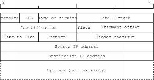
The version field should contain the value `four' for the current version of the Internet Protocol. This field can be used to let different versions coexist, something which will make the transition to a new version much easier.
The IHL field contains the `Internet Header Length'. This specifies the length of the header in 32-bit words. Since it is a 4-bit value, the maximum length of the header will be sixty bytes. Also, since the mandatory part of the header consists of five words, the smallest legal value is five. The specification in 32-bit words also has as a consequence that the header must end on a 32-bit boundary, so it is possible that some padding is required if options are present.
The next field is the Type of service (TOS) field. This field was meant to supply a quality of service (QoS) mechanism, but in practice it is rarely used. However, since voice data has real-time aspects, it may be necessary to pay attention to it if we want to keep the end-to-end delay in the communication low.
An overview of the TOS field is depicted in figure 2.5. The contains a three-bit precedence field which specifies the priority of the packet. A value of zero indicates a normal priority and a value of seven indicates the highest priority. Following the precedence field, there are three bits which stand for delay, throughput and reliability. Only one of the bits can be set to one. The last two bits in the field are currently unused and should be zero.

The size of the IP datagram is specified in the Total length field. It is a 16-bit field, so the maximum size is 65535 bytes. Most networks cannot handle this size so usually it is much less. All hosts are, however, required to be able to send and receive datagrams with a length of 576 bytes or less.
During the transmission of a packet it is possible that it has to traverse different kinds of networks. Each network has its own Maximum Transfer Unit (MTU) which specifies the maximum frame size it can handle, including the link layer header and trailer (if present). This means that there is always a possibility that the datagram, as it passes over the different networks, cannot be transmitted over a certain network. It then has to be fragmented and each piece has to be sent separately.
The identification field is an aid in reconstructing fragmented datagrams. Each datagram fragment will have the same value in this field. When sending IP datagrams, a host typically increments this field for each datagram sent.
Next, there are three flag bits, of which the first one is reserved and should be zero. The next one stands for `don't fragment' (DF) and the last one stands for `more fragments' (MF). If a datagram cannot be transmitted across a network because it is too large and the DF bit is set, an error will be sent back to the sender3. All but the last the fragment of the original datagram will have the MF bit set.
Using the fragment offset field, the internet layer can reassemble fragmented datagrams. This 13-bit value specifies the offset of the fragment in the original datagram. The offset is given in units of 64-bit words.
The time to live (TTL) field is used to limit the lifetime of a datagram. In theory the value specifies the number of seconds the datagram is allowed to exist. There is also the requirement that each router must decrement the value by at least one. If the packets stays a long time in the queue of the router, the TTL value should be decreased with the number of seconds the datagram spent in queue. When the counter is zero, the datagram must be discarded. In practice, the value is just decremented at each router, which makes the field a hop counter.
The protocol field is used to specify to which protocol the data in the datagram belongs. This can be a transport layer protocol, but it can also be one of the control protocols of the internet layer.
The header checksum is used to check the validity of the datagram. Note that the checksum is only for the header, so higher level protocols will have to use their own checksums if they want to make sure their data is valid.
Finally, the minimal header contains the source IP address and the destination IP address. These addresses must be included in each datagram since the internet layer operates in a connectionless way. Each datagram is sent separately and therefore each datagram must contain not only its destination but also its source, in case an error has to be reported. The format of the addresses is described further on.
The options section can be used to record the route a datagram follows, possibly with timestamps. Another option is source routing, where you can specify the route a datagram should follow.
Every host on an interconnection of networks - or internet - which uses IP, should have a unique IP address. An IP address is a 32-bit value and the complete address space is divided into five classes, named class A to class E. The way these classes are represented is shown figure 2.6.

The way an address is usually written, is in its dotted decimal form. To obtain this the 32-bit value is split in four 8-bit values. These four values are then written in decimal form, separated by dots.
The first three classes contain the addresses which can be assigned to hosts. Not all possibilities are allowed though; there are some reserved addresses. First of all, a host ID with value zero does not specify a host, but the network on which hosts with the specified network ID are located.
If the host ID is the highest possible value for its class (all one bits in binary format), the address is a broadcast address for a certain network. This means that if you send IP datagrams to that address, they are delivered to all hosts on that network.
When the network ID of an address is zero, it specifies the local network. This type of address is only used in initialisation procedures, when the local network ID is not known.
Other reserved addresses are 0.0.0.0 and 255.255.255.255. The first of these specifies the local host on the local network. It is also only used in initialisation procedures. The second address is the so-called limited broadcast address. This specifies a broadcast to all hosts on the local network.
Of the remaining two classes, only class D is actually used. Class E was meant for future use. Class D specifies a multicast address. Multicasting allows data to be sent to a group of hosts. This means that when you send an IP datagram to a multicast address, the datagram is sent to all hosts in the corresponding multicast group. Multicasting is explained in more detail later.
The internet layer uses the link layer to actually transmit its data. The link layer, however, can only deliver this data to hosts which are connected to the same medium. To be able to send this data across several networks, routers are used. These devices connect to several networks and make sure that incoming IP datagrams are forwarded to the appropriate network. We will now take a closer look at how this process works. Note that only the basic mechanisms of routing are explained here.
When the internet layer of the sending host has to transmit a datagram to a certain destination, it first examines the destination IP address. This is necessary because the internet layer has to tell the link layer to which machine the data has to be sent. If the destination IP address is on the same network, the machine which will receive the datagram will simply be the destination for the transmission.
If the address does not specify a host on the local network, the internet layer examines its routing table. The entries of such a routing table can be seen as pairs of a destination address and a router address. The destination address can be an address of a host or of a network.
The internet layer then starts looking for a router to send the datagram to. To do this, it compares the destination address of the datagram with the destination addresses in the routing table. If no complete match can be found, it checks if a matching network entry can be found. If not, it uses a default entry. If an entry was found, the internet layer takes the corresponding router address and tells the link layer to send the datagram to that address.
For example, consider a host with IP address 199.198.1.10 who wants to send a packet to 199.198.2.100. This destination host is not on the same network, so the internet layer of the sender will consult its routing table. Suppose that the table looks like this4:
| Destination | Gateway |
|---|---|
| 199.198.5.10 | 199.198.1.251 |
| 199.198.2.0 | 199.198.1.252 |
| default | 199.198.1.253 |
The internet layer first looks in the table for a complete match for address 199.198.2.100. It finds no such match, so it will check for a matching network address. This time, it does find a matching entry: the second one describes the network on which the destination host is present. The internet layer then takes the corresponding gateway entry - address 199.198.1.252 - and sends the packet to that router (gateway).
When the datagram reaches the router, it is passed on from the link layer to the internet layer. The internet layer then follows almost the same procedure to search for a destination machine to forward the datagram to. The only difference is that the router will usually be connected to several networks and this means that the appropriate interface to transmit the data also has to be chosen. The whole procedure is repeated until the datagram reaches its final destination.
To make sure good routes are chosen, many routers communicate with each other. They exchange their routing information and based upon this information each router updates its routing table to contain the best known route for each destination. The type of information and the way it is exchanged are determined by the routing protocol which is used. Examples of routing protocols are the Open Shortest Path First (OSPF) protocol and the Border Gateway Protocol (BGP).
Basically, there are three transmission modes that can be used when sending an IP datagram. They are called unicast, multicast and broadcast. Unicasting simply means sending a datagram from a source to one destination. The term broadcasting is used when you want to send a datagram to all hosts on a specific network. When you want to send a datagram to an arbitrary set of hosts, it is called multicasting.
A simple way to implement multicasting would be to unicast a copy of the datagram to each destination. This method obviously wastes a lot of resources. A better way would be to transmit one datagram which is copied only at points where it needs to follow different routes to reach its destinations. This is the way it is done on IP networks.
To be able to receive datagrams directed to a certain multicast address, a host must first join the multicast group associated with that address. Similarly, when it no longer wants to receive those datagrams, it leaves the multicast group. This group management is done according to the Internet Group Management Protocol (IGMP), which is formally specified in [18].
In general, the protocol works as follows. Each host maintains a list of multicast groups from which it wants to receive datagrams. Multicast routers periodically broadcast IGMP queries on the networks to which they are connected. The hosts then send IGMP replies, containing the groups in which they are interested.
Once these replies have been gathered using IGMP, multicast routers exchange this data with each other and use all this information to build their routing tables. When they receive a multicast datagram, they can then determine to which hosts and multicast routers the datagram should be sent.
When datagrams have to travel across several networks, they will also need to pass through a number of routers. Each router has to examine all incoming packets and this will introduce a certain delay in the communication. Studies even show that the time it takes for a packet to reach its destination is much more affected by the number of hops the packet makes than the actual geographical distance covered [41].
When a router gets too heavily loaded, some packets will have to be discarded. This packet loss is usually bursty. This means that for a short period of time several consecutive packets will be lost.
Routers communicate with each other to dynamically adapt their routing tables to the current state of the network. This means that datagrams going to the same destination can sometimes follow different routes. Although it turns out that routes do not change very often during a transmission, it does happen. Such a change can cause datagrams to arrive out of order.
Besides packet loss and out-of-order arrival of packets, it can also happen that a datagram gets duplicated during its transmission. This will cause two or more identical datagrams to arrive at the destination, possibly with some delay between them.
Finally, another important feature of IP networks is the fact that when a source sends datagrams to a certain destination, the amount of time to reach the destination will differ for each datagram. This is usually called inter arrival delay, inter arrival jitter or simply jitter.
The two most common transport level protocols in the TCP/IP architecture are the Transmission Control Protocol (TCP) and the User Datagram Protocol (UDP). Each of these protocols offers a specific kind of service which applications can use to communicate across networks.
Currently, TCP is undoubtedly the most used protocol of the two. This protocol transforms the unreliable packet-based service of the internet layer into a reliable byte stream. The protocol is designed for communication between two hosts, so it only supports unicasting.
To offer this kind of service, the TCP module has to do a lot of work. First of all, a connection has to be set up, and this has to be done in such a way that it is more or less safe: the module must make sure that connections cannot be established accidentally - for example because of duplicate packets.
The incoming stream of bytes then has to be split up at the side of the sender and the stream has to be reconstructed at the side of the receiver. Care must be taken to discard duplicate datagrams and to correct their arrival order if necessary. There must also be some kind of mechanism to cope with lost packets.
All this is handled quite effectively. To establish a connection the TCP module uses a handshake mechanism, called a three-way handshake. Duplicate and out-of-order datagrams are handled by using sequence numbers. Finally, lost packets are handled by an acknowledgement mechanism: all bytes of the stream have to be acknowledged by the destination. If the source did not receive an acknowledgement after a certain amount of time, it sends the necessary data again. The protocol also specifies flow control mechanisms, which prevent the swamping of a slower receiver, and congestion control mechanisms, which try to avoid congestions.
Note that the exact way in which the TCP module works, is a lot more complicated than this explanation makes it seem. For a complete specification of TCP, you should refer to [36].
Applications which do not require the functionality that TCP provides, can use UDP. To transmit data, the UDP module simply passes a UDP header followed by that data to the internet layer which then sends the datagram on its way. This means that just like IP itself, UDP is a best-effort service. No guarantees about delivery are given, datagrams can get reordered and datagrams can be duplicated. The exact specification of UDP can be found in [39].
The UDP header is shown in figure 2.7. The header contains the source and destination ports, which identify the sending and receiving applications. Next, it contains the number of data bytes which must be sent and finally the header contains space for an optional checksum.

Since the service which UDP offers is almost identical to the service of IP itself, it is possible for applications to send UDP datagrams to a multicast address and to receive UDP datagrams from a multicast group.
Delivering speech information in packets has some advantages to the classical telephone system. When you make a `normal' telephone call, a path is set up between you and the destination of the call. You will then have a fixed amount of bandwidth you can use during the whole call.
The major advantage of that approach is that you will have some guarantees about the QoS, since you are certain to have a specific amount of bandwidth available. But this way, a lot of bandwidth is also wasted, because during a conversation there are a lot of silent intervals for each person.
Using VoIP, those silent intervals can be detected. The VoIP application can examine each packet and detect whether it contains speech information or only silence. If the latter is the case, the packet can simply be discarded.
Another advantage is the possibility of compression. With the compression methods available today, it is possible to reduce the requirement of 64 kbps5 for uncompressed telephone-quality voice communication to amounts which are far lower. However, a high compression ratio often means that the voice signal will be of lesser quality. We will go deeper into the domain of compression in one of the next chapters.
So packetised voice has certain advantages to the classical telephone system. But IP is not the only packet-based protocol. Why exactly should IP be used? This protocol was designed mostly for data transport, and it has only limited QoS support. The main reason IP is so important is because of its omnipresence. The TCP/IP architecture has proved to be very popular and nowadays it is very widely used. This fact gives IP a great advantage over other protocols.
Alternatives for packetised voice include Voice over Frame Relay (VoFR) and Voice over ATM (VoATM). Both allow better support for real-time traffic than an average IP network. However, these technologies are not used as widely as IP.
With the growth of the Internet - on which IP is used - it has become clear that the current version of the Internet Protocol has some shortcomings. For this reason a new version of the protocol has been devised, now called IP version six, or just IPv6.
This section contains a brief description of the protocol, which was introduced in [20] and later redefined in [21]. The latter reference is the source of the information in this section.
Because of the enormous growth of the Internet, there will soon be a shortage of IP addresses. The current version uses 32-bit values, which can provide enough IP addresses in theory. However, because of the subdivision in classes and the way addresses are allocated within those classes, in practice there are far less addresses available. This lack of addresses was one of the most important reasons for the development of a new version.
Other reasons were the need for better QoS support and better support for security. Also, it turned out that some features of IPv4 were hardly ever used and bandwidth and processing time could be saved by redesigning the protocol. Finally, because the routing tables in routers kept growing, the reduction of their sizes was also an important reason for the design of an improved protocol version.
The IPv6 header is shown in figure 2.8. In this version, the header has the fixed size of forty bytes.

The version field contains the value six. This way, the version of the protocol can be detected and IPv4 and IPv6 can coexist. This will make the transition to the new version easier.
The traffic class has somewhat the same function as the TOS field in the IPv4 header. Using this field, one could specify the type of traffic this datagram belongs to. This could then allow appropriate handling of the datagram.
A flow is defined as a sequence of datagrams which are sent from a certain host to a receiver or - in case multicasting is used - to a group of receivers, and for which the sender desires special handling by the routers along the way. The flow label field can then be used as an identifier for such flows.
The number of data bytes following the header is specified by the payload length field. This is a 16-bit wide field, so the maximum number of data bytes in a datagram is 65535. However, it is possible to create larger datagrams than this field allows. How this can be done is explained further on.
The next header field specifies of what type the header following the IPv6 header is. In the simplest case, this is a header from a higher level protocol. But it can also be one of the extension headers which IPv6 defines. It is because of these extension headers the IPv6 header is somewhat simpler than the header of IPv4. Some fields in the IPv4 header and the different options are now used through extension headers.
Several extension headers are defined. Fragmentation, security, authentication, source routing and many more are all made possible through these extension headers. For a complete description you should consult [21].
Earlier, I mentioned that the payload length of 65535 can be exceeded. Well, this can be done using an so-called `hop-by-hop' extension header. This header has an option called `Jumbo Payload' and allows lengths greater than 65535 to be specified. Such datagrams are often called `jumbograms'.
The hop limit field is a replacement for the TTL field in the IPv4 header. This field limits the lifetime of a datagram by requiring that the value in the hop limit field must be decremented by one by each node that forwards the packet.
Finally, the header contains the source address and the destination address for the datagram, which are 128-bit values.
First of all, there is the larger address space. The 128-bit values should be enough to continue for quite some time. On the entire planet, these addresses would allow for 7 x 10²³ addresses per square meter [9].
Furthermore, because of the way multicast addresses are represented, the scalability of multicast routing should be improved. Also, a new type of transmission, called `anycasting', is available. This type of transmission is used to send a datagram to anyone of a group of receivers.
The header format is simpler than it was the case with IPv4. The IPv6 header has only eight fields, whereas the IPv4 header had at least twelve fields. This allows for faster processing of datagrams. The extension headers give the protocol great flexibility, certainly compared to the limited IPv4 options field.
The concept of a flow is also new to this version. This makes it possible for a certain stream of data to receive special treatment. This feature could prove to be useful for real-time services for example.
Finally, the added support for authentication and security are definitely an important improvement over version four.
The Internet Protocol is a connectionless packet based protocol which offers no guarantees about datagram arrival. Datagrams can even be duplicated or delivered out of order. Other characteristics of IP networks are the delay introduced by routers and inter arrival jitter.
The transport layer - the layer above the internet layer - contains two widely used protocols. The Transmission Control Protocol, or TCP, offers a connection-oriented service where the connection can be considered to be a reliable byte stream. The User Datagram Protocol, or UDP, is merely a transport layer extension to IP and has the same characteristics.
The main advantages of packet based telephony are the possibilities for silence suppression and speech compression. The omnipresence of IP is the main reason why this protocol is a good candidate.
For a number of reasons a new version of the Internet Protocol has been developed. The most important one was the fact that there would soon be no more IP addresses available on the Internet. The new version of the protocol is known as IP version six, or IPv6.