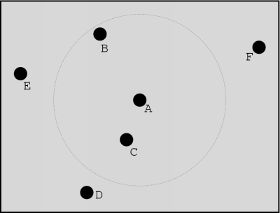
Figure 6.1: Multicasting example
The information in the previous chapters gives an idea about the workings of a general VoIP application. We can now extend this to VoIP in virtual environments.
This chapter begins with an explanation of where the 3D sound should be generated: at the sender or at the receiver. Then, I will present several possible methods for distributing the data. This is followed by a description of how 3D sound can be generated and finally, the involved processing delay is discussed.
When we are using voice in virtual environments, adding a 3D effect to the speech signal will create more realism. But this 3D effect can be generated both at the receiver and at the sender side. Which approach is the most efficient?
When it comes to processing delay, it makes no difference where the 3D sound is created. If it is generated at the sender side, processing will have to be done on outgoing packets for each possible receiver, since they will all need a slightly different effect. If it is generated at the receiver side, processing will have to be done on incoming packets from each sender. So, the net result for these methods will be the same.
But when it comes to bandwidth utilisation, processing at the receiver side has some advantages. To create a 3D effect, a stereo sound signal is needed. This means that when the 3D sound is generated at the sender, the mono speech signal will be converted into a stereo one, which needs at least twice the amount of storage space. Consequently, when this data is transmitted, it will need at least twice the bandwidth as the unprocessed data. Furthermore, due to the 3D effect, the data which has to be transmitted will differ for each receiver. This eliminates the possibility of multicasting the data to reduce the required bandwidth.
In contrast, when the 3D sound is generated at the receiver side, the sender can distribute the mono data which is the same for all receivers. This requires less bandwidth than a stereo signal and it also allows the sender to multicast this information, making very efficient use of the available bandwidth. Note that using this approach, the receiver must somehow know the position of the sender of the data to be able to generate the 3D effects.
Now that we know that it is best to distribute the mono speech data to the necessary receivers, we have to determine a way to do this. Note that not all participants in the virtual environment will be interested in this data: some will be so far away that after the 3D processing step, the resulting sound will not be audible.
In this section I will describe some ways to distribute the speech data. First, a method using unicasting is described and next, some methods involving multicasting are given.
When you are using unicasting to distribute the speech data, you will send a copy of the data to the appropriate receivers. It is obvious that multicasting would be more efficient, but it is possible that this service is simply not available.
The advantage of unicasting is that the sender can control exactly who receives the data. The sender simply looks up the participants who are close enough to `hear' him, and sends the voice information to those destinations.
Multicasting is a more efficient way to distribute data, since the sender only has to transmit one copy of the data. This data is duplicated only when it has to be forwarded over separate links. Still, there are several approaches that can be taken.
One possibility is to use one multicast group for the whole virtual environment. In this case, each participant will receive all the data that is being transmitted, even the data from senders which are too far away. The receivers themselves should then determine whether to process the incoming data, based upon the distance of the sender.
The main disadvantage of this method is that possibly a lot of participants receive unnecessary data, which obviously wastes bandwidth. However, when the virtual environment is quite small, this approach can prove to be very useful, since almost every participant then needs to receive the data from other participants. Also, when only one multicast address can be used, this technique might still prove to be more efficient than using unicasting to transmit the data.
The most efficient way to distribute the data is by assigning a single multicast group to each participant. Each participant then only sends data to its own multicast address, and only if there are other participants within a certain range. To receive the appropriate data, a participant joins the multicast groups of other participants which are in range.
As an example, consider the situation in figure 6.1. Here, the black dots represent participants in a virtual environment and the dotted circle marks the range for participant A. Like the other ones, participant A has its own multicast group and will send its voice data to it since there are other participants - namely B and C - in range. Participant A will also join the multicast groups of B and C, since he wants to be able to `hear' them. The other participants use the same technique.

In contrast to the unicast technique, where it is the sender who decides who receives its speech data, in this case the receivers decide for themselves whose data they want to receive by joining the appropriate multicast groups. From the point of view of security, this solution is not as safe as the unicast solution since basically everyone can hear what everyone has to say. However, the distribution of data is far more efficient than it is in the unicast case.
When speech data arrives at the receiver, 3D effects have to be added to it; we have to spatialise the sound. How this can be done, is covered in this section. First, we will see how sound is perceived as coming from a specific position. Next, it is explained how it is possible to generate 3D sound. The following information is mostly based on [1], which presents an excellent introduction into these matters.
The reason that we can localise the source of a sound quite accurately is that we have two ears. At each ear, a slightly different signal will be perceived and by analysing these differences, the brain can determine where the sound originated.
When a sound source produces a sound wave, the length of the path to each ear can differ. This is illustrated in figure 6.2. How much this difference is, depends on the relative angle of the head to the sound source.
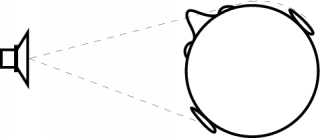
In normal circumstances, the speed of sound in air is about 343 meters per second. So when the length of the path to each ear differs, the sound will reach one ear before the other. This effect is called the Interaural Time Difference (ITD). The ITD is a first indication to the position of the sound source.
The importance of the ITD is frequency dependent. This is demonstrated in figure 6.3. The figure shows two signals: a low frequency signal (above) and a high frequency signal (below). The full line represents the sound wave reaching the ear closest to the sound source (at time t1), the dotted line represents the signal at the other ear (at time t2).
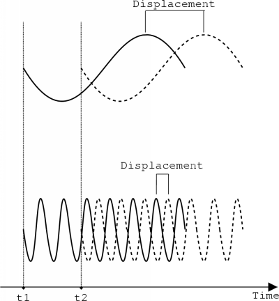
In the low frequency case, the time difference is accurately given by the displacement in the signals. However, when a high frequency signal is perceived, the information is ambiguous. This is because the actual difference in the signals covers several cycles. Once the signals are overlapping, this cannot be determined anymore since the displacement will always seem to be less than one cycle.
The intensity of a sound wave decreases as it travels through the air. Since the path length to each ear can differ, this implies that the intensity of the signal at each ear will differ. This difference is called the Interaural Intensity Difference (IID).
When the head is `in the way' of the sound wave, the IID is also frequency dependent. When the wavelength of the sound is large relative to the diameter of the head, the intensity difference will be rather low. But when the wavelength is small, the intensity difference can become quite large. This is called the head-shadow effect.
Note that the ITD and IID are complementary. At high frequencies, the IID is the most important cue for localisation, but at low frequencies the ITD provides the most accurate information.
The fact that ITD and IID are the primary cues for localisation and the fact that they are complementary is stated in the so-called Duplex Theory. This theory was developed by Lord Rayleigh about a century ago.
When we only take the distance of the sound source to each ear into account, it is clear that there is no way to make a distinction between front or back and above or below. So there must be some other factors which allow us to localise sounds.
The outer ear or pinna also plays an important role in the localisation of sounds. Because of its shape, it boosts some frequencies, while others get dampened. With which frequencies this happens, highly depends on the position of the sound source. This effect causes the pinna to help a lot in localising the sound source.
Because of the rather small sizes of the pinna and its folds, it is mainly the higher frequencies which are transformed. The brain is therefore better able to localise higher frequency sounds than lower frequency sounds.
Range estimation is not yet well understood, but there are several known factors. A first indication of the distance to the sound source is given by the loudness of the sound. A sound coming from far away tends to sound a bit muffled, while a near sound is more clear. But it is not only the loudness that is important, but also the nature of the sound. For example, if you are far away, you will not seem to be close if you yell. This is because sounds produces by yelling and talking have different characteristics.
Turning the head also helps to determine the range of a sound source. The change in angle to a sound source that is close is larger than the change for a source that is further away. This is illustrated in figure 6.4. Part (a) of the figure shows two sound sources with the same angle to the right ear. When the head is turned, shown in part (b), the change in angle to the closest sound source is larger than to the other source. This helps the brain in determining the distance to a sound source. The effect is called `motion parallax'.
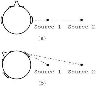
The IID also provides some information to determine the range of the sound source. The intensity of the sound decreases inversely with the square of the range. This causes the IID to be large for close sound sources. An example of this is when you hear an insect buzzing in one ear.
When you are in a room, you do not only perceive the sound wave coming directly from the sound source, but also a lot of sound which has been reflected off objects. This type of sound is referred to as reverberant sound. Reverberant sound does not differ as much with the distance to the listener as the direct sound. Therefore, the ratio of direct to reverberant sound is also a cue to the range of the sound source.
With the knowledge of how sound is perceived as coming from a specific location, we can try to simulate this effect. We do this by transforming a mono sound signal into one which seems to be coming from a certain position. Since the key to 3D sound is the different signal at each ear, the resulting sound signal will be stereo.
A sphere can be used as a simple model for the head. Given the positions of a sound source and the listener, this model can be used to calculate the path of the sound to each virtual ear. This information can then be used to calculate ITD and IID. For accurate results, the curvature of the sphere should be taken into account.
Figure 6.5 illustrates this model. The figure shows how the path of the sound differs for each ear. When the sound source is at an angle q and the head radius is R, the sound will have to travel an extra distance of R.q + R.sin(q) to reach the ear which is furthest away.

Using this information together with the knowledge that the speed of sound is about 343 meters per second, we can calculate the time it takes for the sound to reach each ear. We then simply have to insert the appropriate amount of delay for each channel in the stereo signal to give it the correct amount of ITD.
Using the path length for each ear, it is also possible to calculate the basic part of the IID (without taking the head-shadow into account). It is known that under normal circumstances the intensity level of sound decreases with approximately six decibels as the distance increases with a factor of two [2]. The relationship between the decibel scale and the amplitude is given by


This formula can be simplified further, and this gives us approximately the following relationship:

Note that `distance' is calculated from the centre of the virtual head of the participant who produced the sound. This means that it will always be at least `headradius', which is the radius of the virtual head of that participant.
As you can see, this formula indicates that the original amplitude simply has to be multiplied with a factor that depends both on the distance and the head radius. When this formula is applied for the distance to each ear, this will result in a certain IID.
As was mentioned above, these calculations do not take the head-shadow effect into account. To do this, we have to determine a filter which depends on the angle to the sound source and which dampens the high frequencies when the head is in the way. More information about modelling the head-shadow effect can be found in [1].
In my own implementation I have used a simpler model than the one above. To calculate the distance, I have not taken the curvature of the head into account. I have simply calculated the distance from each ear to the centre of the sound source. This is illustrated in figure 6.6.
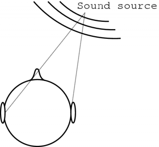
In my application, the 3D effect was created by using this model and the ITD and IID calculations mentioned above. I also added some reverberation to make the sound a bit more spatial. Personally, I found the result quite good.
By using only ITD and IID in the creation of a 3D sound, it is not possible to make a distinction between front and back or above and below. Also, the sound still seems to be coming from inside the head: there is no sense of externalisation. To solve these problems, more sophisticated techniques have to be used.
Basically, what we need to know is what a sound signal looks like when it reaches each eardrum. We already know that ITD and IID will be introduced, but a lot of other effects also occur, like reflections by the pinna for example.
We can model the transformation which occurs at each ear as a variable linear filter. It is variable because the effect differs according to the position of the sound source. For a linear filter, it can be shown that if we know the filter's output to an impulse, we can calculate its output to any signal [11]. The output of a filter to an impulse is called the impulse response for that filter.
So if we can find out what signals reach the eardrums in response to an impulse, we can determine its response to any signal. This impulse response is called the Head-Related Impulse Response (HRIR). Note that the HRIR still depends on the position of the sound source and in general will be different for each ear.
The representation of a HRIR in the frequency domain is called a Head-Related Transfer Function (HRTF). Like with the HRIR, with each position there are two related HRTFs: one for each ear. When you look at these signals, you can clearly see which frequencies get boosted and which ones get dampened.
One way to obtain the HRTF information is by actually measuring them. Usually, this is done by using a model of the human head, in which microphones are present at the ears. A well known model is the KEMAR model. KEMAR stands for `Knowles Electronic Manikin for Acoustic Research'. Measurements which are made with this model are available to the public, which makes this method quite easy to use.
There is a disadvantage to the use of these measured HRTFs. Because the shapes of the head and the pinna differ greatly from person to person, these standard measurements will not create a good 3D effect for several people. The ideal solution would be taking measurements of the listener's HRTFs, but this consumes a lot of time and effort.
Another solution is not measuring the HRTF information, but modelling it. This way, a number of parameters could be set by the user to generate a good 3D effect. More information about such models can be found in [1].
If headphones are used, it is not difficult to generate a specific signal for each ear, since there is no interference of the two signals. But some headphones tend to transform the signal somewhat, which makes localisation less accurate. Also, localised sounds coming from a headphone often seem too close because of the closeness of the actual sound source.
Speakers generally do not cause such problems, but there is another problem: the signals from the speakers interfere with each other. It is possible to create the signals for each speaker in such a way that the resulting signal at each ear is still correct, but it is computationally quite intensive. Also, the listener has to be sitting in the right spot and cannot turn his head too much.
Personally, I have used headphones and found the results quite adequate. This is computationally very simple, especially since I only used a very simple model to create 3D sound. Another advantage of headphones is that no echo is generated when a microphone is near.
Transforming a mono speech signal into a stereo one which seems to be coming from a certain position will require several calculations which, in turn, introduce delay. Depending on the realism to be achieved, the delay can vary greatly.
The simple technique I have used in an application requires almost no CPU power. The distance from each ear to the sound source is first calculated. Then, the appropriate amount of delay is inserted for each channel and the amplitude of the signal is adjusted. This does not require many calculations.
When HRTFs are used, the calculations are more demanding. Note that for each ear the calculations have to be done separately. Depending on the desired realism, the required calculations still vary a lot. When the calculations have to be done for only a few sound sources, it can normally easily be done in real-time by software. However, when many sources have to be processed, it may not be possible to do this anymore. Fortunately, many soundcards already have the ability to generate 3D effects, so we can relieve the CPU of this task.
When several participants in the virtual environment are speaking at the same time, a receiver needs to have enough bandwidth available to receive their voice data. When you have direct access to a LAN, this is probably not a problem. But when you are using a dial-up link, the necessary bandwidth might simply not be available, even when severe compression is used.
A solution to this problem is to place a machine which mixes the signals for a specific participant before the link. This is depicted in figure 6.7. In this figure, the dial-up link is directly to the mixer, but this is not necessary. The only thing the mixer needs to do, is to generate the appropriate 3D effects for the user's position, mix the signals from the sound sources together and transmit the resulting data to the user. The user will then only need bandwidth for one stream, which is achievable over a dial-up link. Note that this will introduce some extra delay.

To make a sound appear to come from a specific position, it is necessary to generate a stereo signal. Because of this, it is more efficient to add 3D effects at the receiver side, since then we only need to transmit a mono signal. This way, we can also make use of IP multicasting because the same data can be sent to all receivers.
One way to distribute the speech data is to use unicasting. It allows the sender to determine who receives the data, but it wastes bandwidth. More efficient distribution can be achieved by using multicasting. However, this way the senders cannot determine who receives the data. It is then up to the receivers to decide which data they need to process and which not.
Sounds are perceived as coming from a certain point because each eardrum receives a slightly different signal. From these differences, the brain determines the position of the sound source. Two important cues for localisation are Interaural Time Difference (ITD) and Interaural Intensity Difference (IID). The outer ear or pinna also plays a very important role in the localisation of sounds.
Using ITD and IID, it is possible to create basic 3D effects. However, this way it is not possible to create distinction between front and back or above and below. Better results can be achieved by simulating the transformations of the sound signal before it reaches the eardrums. These transformations are described by Head-Related Transfer Functions (HRTFs).
Because there can be several sound sources at the same time, it is possible that the calculations to generate 3D sounds are too demanding. It may then be necessary to let hardware perform the localisation of the sound. For the same reason, the necessary bandwidth may not be available, for example when using a dial-up link. A solution is to let a machine before the slow link apply the 3D effects and let it send the mixed signal over the link.