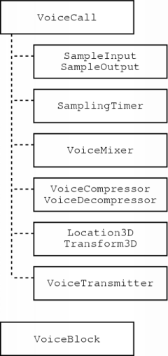
Figure 9.1: VoIP framework layout
After the creation of JRTPLIB, I started designing a VoIP framework, which is described in this chapter. I designed this framework because I wanted to be able to easily create several VoIP test applications. By separating the VoIP components from the rest of the application, this task is much simpler. Furthermore, I wanted to create it in such a way that would allow testing of different components, for example different compression techniques.
This work led to the C++ framework described in this chapter. First, I will present the general structure of this framework. Afterwards, its implementation is discussed.
The structure of the framework is depicted in figure 9.1. The VoiceCall class is the one which connects several components. As you can see, these components are pretty much the ones described in this thesis.
The SampleInput and SampleOutput classes are the ones responsible for grabbing and reconstruction of voice signals.
In the framework, the intervals for both capturing the voice signal and playback are assumed to be the same. The SamplingTimer class is responsible for indicating when this interval has elapsed.
With VoIP in virtual environments, there can be several persons speaking at the same time. The VoiceMixer component is responsible for mixing these signals together. This component gives the SampleOutput class a new block of speech data when an interval has elapsed, so it must make sure that everything is in the correct order.
The VoiceCompressor and VoiceDecompressor classes compress and decompress a block of speech data respectively.
For VoIP in virtual environments, the sender of speech data has to include some information about the position of the sender. This is done in the Location3D class. The actual 3D effects are added at the receiver side by the class Transform3D.
Somehow, the speech data will have to be transmitted and received. These tasks are the responsibility of the VoiceTransmitter class.
The VoiceBlock class is used as a container for voice data. An instance of this class is passed between the previously listed components to make VoIP possible. This class has member functions indicating properties of the data, for example the sampling rate, so that each component can process the data correctly.
In this basic framework, only the VoiceCall and VoiceBlock are really implemented, the other classes are abstract. Using inheritance, this allows us to try several different techniques. For example, we can easily try several compression schemes by implementing them in classes inherited from VoiceCompressor and VoiceDecompressor.
In this section I will cover the implementation of the framework. First, I will explain how the VoiceCall class uses the other components to make VoIP possible. Then, the components themselves are discussed.
The VoiceCall class contains several members to set up the different components. When this is done, the application only has to call the `Step' member function to make VoIP possible. The outline of this function is depicted in the pseudocode below.
VoiceCall::Step()
{
    // Check if the sampling interval has passed
    if (samplingtimer->HasTimeOut())
    {
        // Get a sampled block and start sampling again
        sampleinput->GetSampleBlock(&inputblock);
        sampleinput->StartSampling();
        // Get a block from the mixer and play it
        mixer->GetSampleBlock(&outputblock);
        sampleoutput->Play(&outputblock);
        // Restart the timer
        samplingtimer->RestartTimer();
        // Prepare block for transmission and transmit it
        if (add3Dinfo)
            location3d->Add3DInfo(&inputblock);
        if (compressblock)
            compressor->Compress(&inputblock);
        transmitter->SendBlock(&inputblock);
        // Adjust the current sample offset
        mixer->GetSampleOffset(&sampleoffset);
        transmitter->SetSampleOffset(sampleoffset);
        // Poll for incoming data
        transmitter->Poll();
        // Add input from the connection to the mixer
        for (each voice source)
        {
            while (this source has data available)
            {
                // Get some data and process it
                transmitter->GetSampleBlock(&block);
                if (decompressblock)
                    decompressor->Decompress(&block);
                if (add3Deffects)
                    transform3d->Create3DEffect(&block);
                // Send processed data to the mixer
                mixer->AddBlock(&block);
            }
        }
    }
}
|
In principle, this function should be called continuously to assure that the necessary actions are taken at the exact point when the sampling (and playback) interval has elapsed. However, one could implement the abstract classes in such a way that the application only calls the `Step' function when necessary. To give an example, you could let an implementation of the SamplingTimer send a signal to the application when an interval has elapsed. In turn, the application can then call the `Step' function.
The pseudocode should be quite clear, but it may be necessary to explain what the sample offset is for. When voice data is received, it is put in a VoiceBlock instance. This will also hold information about when this data will have to be played, expressed in terms of samples. This timing information is used by the mixer to insert this data at the correct position in its output stream. When the mixer passes a block of data to the playback routine, the sample number of the first sample in its queue has changed. It is this value that is passed to the transmission component.
The current sample offset is needed each time a participant joins in. The timing information in the packets of this participant only provides information about when the data should be played, relative to the start of the participant's transmission. To provide the correct timing information for the mixer, the current sample offset has to be added to the timing information in the packet.
There is another use for the current sample offset. After having calculated the timing information for a block of voice data, the transmitter can easily see if it is still possible to play this data: if the sample offset of the block is smaller than the current sample offset, it is useless to process the block any further since its playback time has already passed. The transmitter can then simply discard the data.
The grabbing and reconstruction routines are rather straightforward. They simply use the operating system's capabilities to either record or playback speech data. I have made such routines for both Linux and MS-Windows platforms.
On both platforms, I have implemented SampleInput and SamplingTimer in one class, using multiple inheritance. This way, I could use the recording interval as timing information.
At the end of each sampling interval, the mixer sends a block of data to the playback routine. For this reason, I have implemented the mixer using a linked list of such blocks. Initially, these blocks contain only silence.
Each time the mixer receives a block, it adds the data to the blocks in the list. Because of the principle of superposition mentioned in chapter three, the data simply has to be added to the data which is already present.
Because of the structure of the framework, it was easy to try several compression schemes. The first scheme I implemented was the simple silence suppression technique which I described in chapter three. This silence suppression scheme was also used in the other compression methods which I implemented:
To my own opinion, the simple DPCM technique produced the most acceptable results. The delta modulation method simply could not reproduce the signal accurately enough. The wavelet coding technique could do this, but to achieve the same quality as the DPCM technique, the required bandwidth was comparable to that of DPCM.
I have also tested a Linear Predictive Coder, using a library which provided the LPC coding and decoding functions. The resulting communication quality was very good, but the speech signal did sound somewhat synthetic.
To allow somebody to choose a compression technique at run-time, I created a wrapper class for these compression modules. If all users in a session use that wrapper class as the compression and decompression module, each user can select the compression scheme he prefers.
At the sender side, the sender's position was added to the data. This information was then used by a receiver, together with its own position, to create a localised effect. The technique used was described in chapter seven.
The transmission module was implemented using RTP to send the data. The RTP functionality was provided by JRTPLIB, which made the implementation of this module both easier and faster. No additional work was done to provide QoS.
Because no QoS guarantees can be given, this module tries to stay synchronised as good as possible. When too many consecutive packets from a certain source have to be discarded, the module resynchronises with that source.
Also, as was mentioned in chapter three, the amount of buffering is determined using jitter information provided by RTCP packets. Buffering is simply done by adding some value to the timing information of a block with speech data. This will cause the mixer to insert the block further on in its linked list and this, in turn, will cause the data to be played back a bit later.
The module also filters out any duplicate packets. When the same data is passed to the mixer several times, that piece of the signal will sound much louder because of the principle of superposition. Such a discontinuity is very disturbing when VoIP is used in 3D environments.
The only1 real problem I encountered was with the original design of the framework. In the first version, there was not one single `Step' routine. Instead, there was one routine which covered the input and one for the output. The timing had to be done by the SampleInput and SampleOutput modules. While this allowed the recording and playback intervals to be different, it was not possible to get these intervals low enough. The problem seemed to occur because the timing information provided by playback was not accurate enough.
I then started rewriting the framework. The timing function was put in a separate component and the routines for input and output were combined in one single `Step' function. This is the structure which I still use today and I am now able to get the recording and playback interval as small as I want: even a one millisecond interval is no problem.
To be able to easily create some VoIP test applications, I first developed an object-oriented VoIP framework in C++. This framework was also designed to try out several techniques to realise a specific VoIP component, for example different compression techniques. The structure of this framework reflects the components described in this thesis.
The basic framework contains a lot of abstract classes, representing VoIP components like the transmission or the playback component. Inheritance can then be used to actually implement a component. This is the mechanism which allows to try out several versions of a component.